
The UREI 1176 Peak Limiter is a classic audio compressor
designed by Bill Putnam, first built in 1967, making use of FETs
and using them as a variable resistor to control the gain reduction in the circuit.
The 1176 has been employed in countless recordings over the years and it is still
used by almost every recording studio...
If you cannot afford a new unit (e.g.
Purple Audio MC 77 or
Universal Audio 1176LN ),
then DIY is the best way both to save money
and to get great satisfaction.
On this web page I just try to give you the basic information and tips to build your own unit.
Essentially this is a collection of wise advices of some guys on the web (found on forums, newsgropus, web pages)
that are much more experienced than me.
I'm very grateful to these people for what I've learned and what I could do with their teachings.
Acknowledgments are at the bottom of the page.
Index
- Introduction
- Which revision to choose?
- How it works
- Schematics and PCBs
- The Bill of Materials (BOM)
- Etching PCBs
- FET matching
- Assembling and wiring
- Calibration and measurements
- Sound clips
- Links
- Acknowledgments
1. Introduction
Back to top2. Which revision to choose?
Back to topNow, let's have a look at a simplified description of each revision:
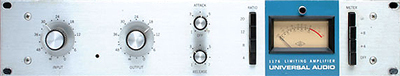
Figure 1. Revision B (AKA "Bluestripe")
- Revisions A and B. Also called "stripe" are the basis for all the other revisions. The signal and line amp are based on the 1108 microphone preamp and use a FET as the first active component in each amp stage. The sound is characterized by a small amount of distortion due to the lack of the low noise circuitry (introduced in later revisions).
- Revisions C/D/E. Many current reissues are based on these revisions including Purple Audio MC77 and Universal Audio 1176LN. These revisions have got a blackface front and have the suffix "LN" which stands for "low noise". In fact all of the circuit changes are intended to reduce noise and distortion.
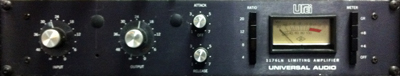
Figure 2. Revision D (AKA "Blackface")
- Revision F. In this unit the class A 1108 preamp is replaced by a "push-pull" amplifier based on 1109 style class AB preamp with an output transformer that gives more output gain and a slightly different sonic character. Rev. F switches from a discrete to opamp based metering circuit.
- Revision G. This revision removes the input transformer in favor of an IC differential amplifier. The output is class A/B and it uses a B11148 output transformer. F and G are the cleanest revisions as they measure the lowest harmonic distortion resulting in a less colored sound, although preserving the 1176-style compression.
I chose rev. F for a variety of reasons:
- It is probably the easiest (and cheaper?) to build and the most thoroughly documented of all DIY 1176 projects.
- Jakob Erland (Gyraf Audio) made his own DIY version based on UREI rev. F making it simpler for various aspects and great for DIY.
- Mnats (the Bill Putnam of the DIY world) offers an updated PCB version of Gyraf's one.
- Many parts lists and successfully completed projects are available on the web.
3. How it works
Back to topFigure 3 shows the block diagram of the 1176.

Figure 3. 1176LN Block diagram
Signal compression is performed by the gain reduction stage (GR circuit, preamp and GR control circuit). The input section has a potentiometer to control the amount of attenuation, followed by the transformer. The signal attenuation helps not to overdrive the FET in the gain reduction stage.
Compression is achieved by a FET, used as a variable resistor. The signal used for gain control is sensed after the gain reduction (feedback style compression) and it is fed to the gate of the FET. The greater voltage is applied to the gate the more amount of gain reduction is achieved.
The output stage is a push-pull (class AB) amplifier followed by the output transformer, that forms an integral part of the feedback network and it is used to stabilize the output stage. For further information visit NRG Recording's DIY site.
4. Schematics and PCBs
Back to topI was looking for something I could etch on my own, so I used Mnats' rev. H version, which is nearly identical to his rev. J version.
Figure 4. The Schematic for the 1176 compressor, Rev #F.
The schematic used is the original UREI rev. F schematic (Figure 4).
Here you can find a list of features of Mnats' rev. H/J PCBs.
Briefly, Mnats' boards introduce these features:
- Fix ground loop problems of Gyraf's version, grouping the ground points in each circuit block and returning each group separately to a central star point.
- The ability to mount BD 135/136 or BD 139/140 output transistors without crossing leads.
- The option to mount Lundahl or OEP transformers and the ability to install the Lundahl "reversed" to increase gain equivalent to the original UREI 1176.
- Additional pad for stereo interconnection (of two units).
- Additional pads for mounting various styles of trimmers and capacitors.
Also, if you're wondering which one transformer to choose, Lundahl or OEP, here you can find an interesting discussion about this question. To be very concise, it seems that the OEPs have more "iron" sound with a dark tone, while the Lundahls are more clear and defined on high frequencies. I chose Lundahls for this reason and for their quality too, though they cost five times more than the OEPs.
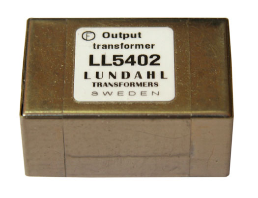
Figure 5. Lundahl LL5402 Output Transformer.
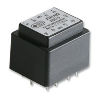
Figure 6. OEP A262A2E alternative Output Transformer.
5. The Bill of Materials (BOM)
Back to topI bought components from "only" three suppliers: Mouser, Canford and Hairball Audio.
I’ve got all semiconductors, diodes, resistors, capacitors, potentiometer, knobs, etc… from Mouser. I bought the SIFAM AL29WF VU-meter and the two Lundahl transformers LL1540, LL5402 from Canford (they've got OEPs, too). Then I bought the toroidal transformer from Hairball Audio and the 19″ 2U chassis and blank PCBs from a local store. You can download my BOM (1176_bom.xls), and Mnats' parts list for rev. H/J PCB.
6. Etching PCB
Back to topWhat you need:
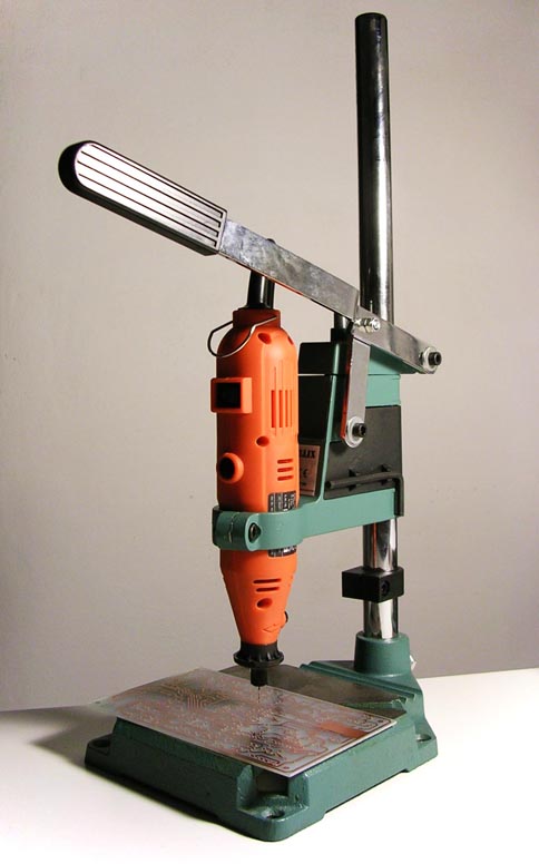
Figure 8. My drilling machine.
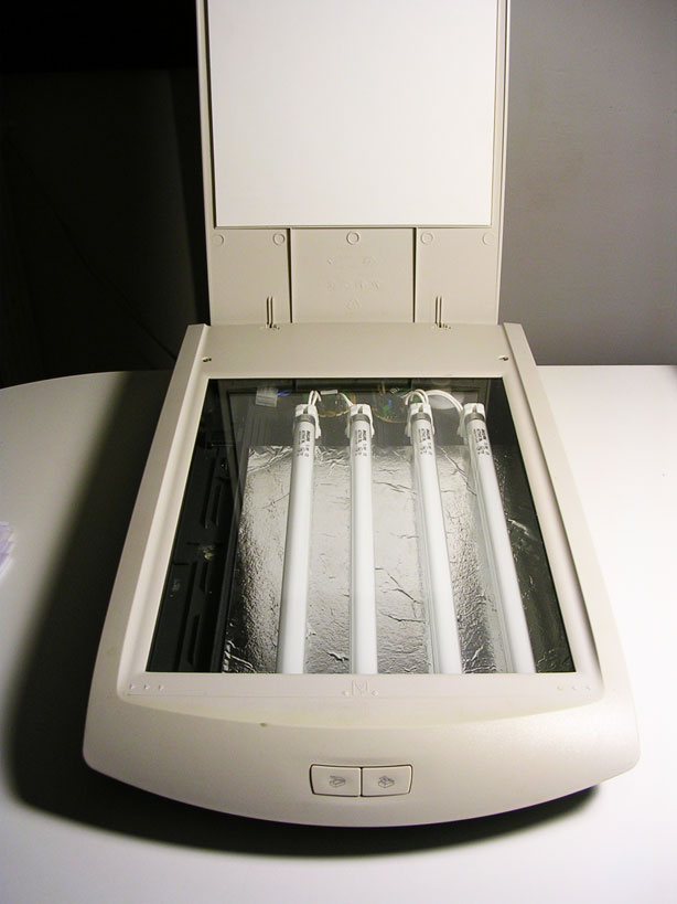
Figure 7. My DIY bromograph.
- Transparency (acetate) paper.
- A PCB with positive photoresist layer.
- A source of light for explosion (a standard light bulb works well but UV lamps do the job better and faster).
- Sodium hydroxide (caustic soda, NaOH) for development and an etching solution like ferric chloride (FeCl3).
- Acetone or a nail polish remover.
- Protective gloves.
- Protective coating lacquer for PCBs (Plastik 70).
- A drilling machine.
- Print the circuit's layout with a quality laser printer on acetate paper. Printing two copies and overlapping them helps getting better results during exposition.
- Expose the PCB. With my bromograph it takes 1-2 minutes.
- Develop the PCB in a solution of sodium hydroxide and water (7 g/l). This step takes about 1 to 5 minutes (depending on temperature). Don't heat the solution and don’t touch the photoresist layer during development.
- Etch the board in a solution of ferric chloride. The trick here is to warm up the solution (up to 45°C) to speed up the process (from 20 minutes at room temperature to 5 minutes with the heated fluid).
- Clean the PCB with acetone to strip the photoresist away.
- Protect the copper from oxidation by spraying a coating for printed circuit boards (Plastik 70).
- Drill (0.8 mm, 1 mm and 1.5 mm HSS bits).
- Check traces (continuity).

Figure 9. Etched PCBs (Mnats' rev. H).
7. FET matching
Back to topI followed the procedure described here using a simple test circuit quickly implemented on a perforated board.

Figure 10. FET matching.
- Two 9V batteries (or a +/- 10V power supply).
- A digital multimeter.
- An IC socket (to swap FETs).
- A few components: 2 x 10 KΩ resistors, one 5 MΩ resistor and one 10 KΩ trimmer/potentiometer.

Figure 11. FET matching.
Figure 12. FET matching.
See 1176_fet_matching.xls spreadsheet.
8. Assembling and wiring
Back to top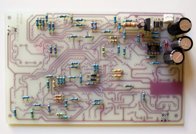
Figure 13. Building up power supply first.
The components you need to place are: R85, R86, R87, R89, C23, C24, C25, C26, VR1, CR6, CR7, CR8, CR9, CR10.
You can also place other resistors, but don't place any transistor or IC.
I suggest to mount the 1 Watt resistor parallel to the board to enhance cooling. Remember to mount the heat sink on the 7824 (not showed in figure 13).
2. Wire transformer.
Figure 14. Transformer connection diagrams.
3. Test positive/negative voltages before mounting other components. The two supply rails are +30V/-10V. Check the schematic to determine where to test these voltages.
4. VU-meter lamp resistor. I don't use VU-METER lamp connector on the PCB since it provides 36VDC while my lamp requires only 12V (I'm using the Sifam illumination kit for AL29WF). The lamp doesn't care if you supply AC or DC, so the simpler solution is to take 0-24VAC from one rail of the transformer and drop it to 12VAC using a resistor.
A voltage drop (ΔV) of 12V is required, and the lamp needs I = 100 mA of current. Some basic math with Ohm's law:
R = ΔV/I = 120 Ω, P = RI2 = 1.2 W.
But... this is theory. In practice, the trasformer secondary voltage, even under load (of the 1176 circuit) is around 28V. 11V of voltage drop across the lamp is enough to give a reasonable glow. We need to drop ΔV = 28V-11V = 17V. So we have:
R = ΔV/I = 170 Ω. The resistor dissipates an energy of P = RI2 = 1.7 W.
I found a big ceramic 180 Ω, 5W resistor and used it with success. I suggest to make use of a resistor > 170 Ω to decrease the voltage drop across the lamp in order to increase the lamp's life. Make sure to place this resistor in the case without touching other wires because it will get hot.
5. Star grounding: connect input XLR pin 1 to chassis. This helps to keep hum to a minimum.
6. For more details check Mnats' Wiring Guide.
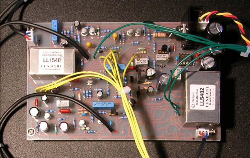
Figure 15. Fully assembled Mnats' rev. J PCB.
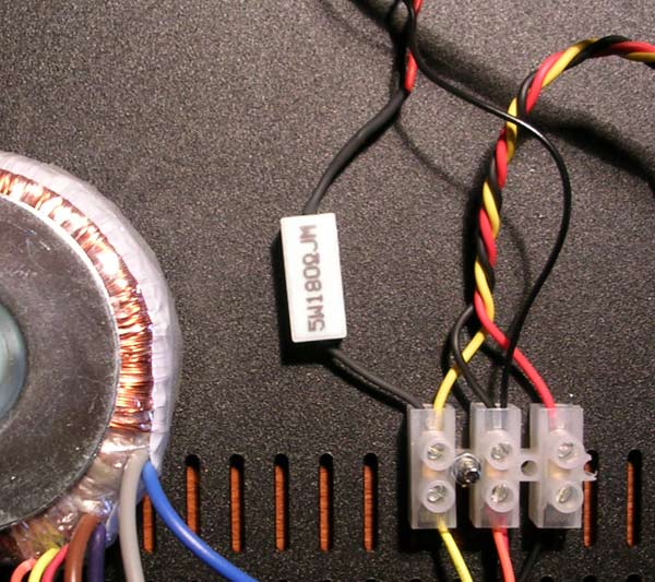
Figure 16. Vu-meter lamp resistor.
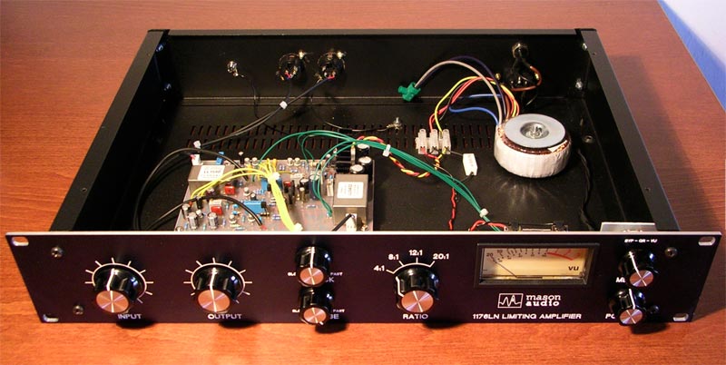
Figure 17. Inside...
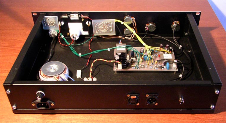
Figure 18. Inside...
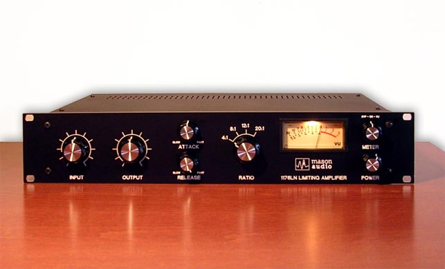
Figure 19. Completed 1176LN clone.
9. Calibration and measurements
Back to topFor this procedure you will need an oscillator and a voltmeter. If you haven't got a signal generator you can generate a test tone with your DAW's sound card as well. In this case you need to measure the output signal from the sound card with the DVM and convert Volts to dBu (see this online converter).
You can follow these instructions here and here (.pdf from Greg's website).
Mnats' videos on youtube are a very helpful resource. They're for revision D but you can find them useful as well.
1. Run the unit for 10 minutes to stabilize components' temperature.
2. Make Q-Bias adjustment. This procedure requires bypassing the GR circuit. If you have an attack control potentiometer with integrated SPDT switch, just switch the attack to OFF position. Otherwise you can't bypass the unit just setting the meter to bypass mode (on the "byp-gr-vu" switch) because in this way you will disable the meter. The solution is to short pin 22 to ground to bypass GR circuit withuot disabling the meter.
Then apply a 0dBu (0.775 Vrms) 1kHz sine wave to the input. Adjust IN and OUT pots to get +1VU on the meter. Start with the Q-Bias trimmer fully CCW. Then turn the trimmer CW until the VU meter reads 0VU. Now the FET is sligtly in conduction.
3. GR Meter Zero. With no input signal and meter set to GR mode, adjust the trimmer until you read 0VU on the meter.
4. GR Meter Tracking. Set ratio to 1:20. Set meter mode to VU. Set input and output to 12'oclock. Set release to 12'oclock, too. Set attack to OFF or short pin 22 to ground if the attack potentiometer doesn't have and integrated SPDT switch. Apply a 0dBu 1kHz sine wave signal and adjust the output control until the meter reads 0VU. Remove the shorting leads and observe the drop. Adjust input control to read -10VU on the meter. Then short pin 22 to ground again and adjust the output control to read 0VU. Repeat iteratively this procedure in order to have exactly 10dB of signal drop (you must read 0VU with shorting leads and -10VU without shorting leads). Once you have adjusted input and output control for 10dB drop, don't touch them againg. Select GR mode. With the shorting leads adjust GR meter Zero trimmer to read 0VU. Remove the shorting and adjust the GR meter tracking trimmer to read -10VU. Repeat the procedure until you read 0VU with shorting leads and -10VU without shorting leads.
5*. Distortion Trim Adjustment. This adjustment is optional since the effect on the distortion of the unit is minor, not even audible. You must have a distortion analyzer in order to make this adjustment. Bypass the unit, input a 1kHz 0dB signal. Set unity gain and set the distortion trimmer for minimum distortion.
Once I calibrated the unit, I wanted to measure the compression characteristics of the unit. By the simple procedure described here I obtained the compression curves and the real compression ratios. The unit is performing well, even the compression curves are very similar to those of the original UREI unit (diagram taken from UREI manual).
Figure 20. Compression curves.

Figure 21. Original UREI 1176 transfer characteristics.
From UREI 1176LN manual.
| Ratio | 4 | 8 | 12 | 20 |
| Measured ratio | 5.1 | 8.2 | 11.5 | 20.5 |
The calculation of the "real ratio" was made measuring the relative change in Output for a corresponding relative change in Input at 0dBu (ΔInput/ΔOutput).
See 1176_ratio.xls spreadsheet.
10. Sound clips
Back to topDrums A, Ratio 4:1, Attack 12 O'clock, Release 3 O'clock
Drums A, Ratio 8:1, Attack 9 O'clock, Release 3 O'clock
Drums A, Ratio 4:1, Attack fully CCW (slow), Release fully CW (fast), Hard compression
Drums B RAW
Drums B, Ratio 8:1, Attack 11 O'clock, Release 3 O'clock
Drums B, Ratio 12:1, Attack fully CCW (slow), Release fully CW (fast), Hard compression
Acoustic Guitar
Strumming, Ratio 4:1, Attack 3 O'clock, Release 2 O'clock
Strumming, Ratio 12:1, Attack 3 O'clock, Release 2 O'clock
Fingerpicking RAW
Fingerpicking, Ratio 4:1, Attack 12 O'clock, Release 3 O'clock, Hard compression
Fingerpicking, Ratio 4:1, Attack 12 O'clock, Release 3 O'clock, Soft compression
Fingerpicking, Ratio 8:1, Attack 9 O'clock, Release 3 O'clock
Bass
Bass, Ratio 4:1, Attack 3 O'clock, Release fully CW (fast)
Bass, Ratio 8:1, Attack fully CW (fast), Release 3 O'clock
Special thanks to Nardo and Pissi at Relaxo Studio for providing these audio samples!
11. Links
Back to topMnats.net - Building the DIY Gyraf 1176LN Clone
Nrgrecording.de -UREI 1176 FET Compressor - The Making Of
Greg's DIY G1176 Project
AXT Systems - 1176LN Clone Compressor
GroupDIY Forum
Threads on GroupDIY.com Forum:
All things G1176
OEP vs Lundahl transformers in the 1176
Calibrating G1176
Hairball Audio: 1176 Stereo Linking PCBs Support Thread
Sending Frontpanels: Advise !
Various:
Mouser Electronics - Electronic Component Distributor
Canford - Professional Audio and Video Equipment
Mohog Audio (MoFET76 Limiting Amplifier)
Universal Audio - 1176 Hardware Revision History
Mnats' Channel on YouTube
Link to files:
Schematic: 1176sch.gif
PCB rev. H layer: 1176_revh_bottom.pdf
PCB rev. H overlay: 1176_revh_checkplot.pdf
Mnats' BOM: mnats_1176_bom.pdf
My BOM: 1176_bom.xls
FET Matching: 1176_fet_matching.xls
Compression Ratio: 1176_ratio.xls
Metal work:
Schaeffer AG: Schaeffer Front Panels Service